|


INTRODUCTION
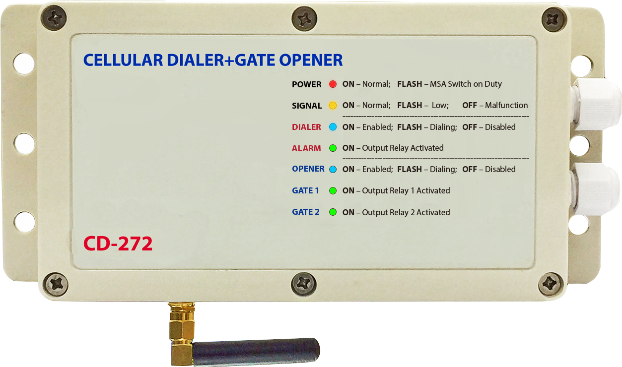
CD-272 is a dual function device that combines Cellular Dialer and Gate Opener in one unit. It is compatible with all our Alarm Control Panels and Access Control Keypads for feature enhancement; which makes a local alarm system to report alarm event to 5 preset telephones and makes keypad to actuate electric door lock via mobile or line telephone. CD-272 is almost compatible with all the alarm control panels & keypads on the market.It will alert the owner and associate users with text message or ring calls to their obile phone or line phone while alarm occurs.
CD-272 has 3 Operation Modes for owner selection to cope with different application environments
Dialer + Gate Opener (default) ---- Both functions are enabled. The system is shared for two functions. Suitable for low access control traffic environment at home or office.
Dialer Only ------------------------------ Dedicates for alarm event reporting; the Gate Opener is disabled.
Gate Opener Only --------------------- Dedicate for Gate Opener; the Dialer is disabled.
Application

FEATURES Dialer & Gate Opener Common Features Master Code for System Feature Programming Authorization Master Code, Owner's Contact Phone Number, System Operation Mode and SIM Card Testing Interval Settings are Authoried with (MSA) Switch (Master-Setting-Authorization) Programmable 1-6 Weeks SIM Card Active Testing Dialer Performs Signal Strength Testing with SMS Testing Command Function and Feature Programming with SMS from Mobile Phone Maximum 30 Characters Including Space SMS Text Execute Dialing Immediately for Alarm Notification after Opener Comment Finish While System Has Been Busy in Dialer + Opener Mode.
Dialer Section Five Telephone Numbers (1 Owner + 4 Auxiliary) for Receiving Alarm SMS and Ring Call. The Owner Number Also Receives System Status SMS. Telephone Number Can be 30 Digits Maximum Three Alarm Notification Formats: 1) SMS + Ring, 2) SMS Only, or 3) Ring Only Two Isolated Input Terminals for Alarm Event Triggers. e.g. Burglar, Fire or Others Input Terminals Independently Selectable for Ring Only to Prevent SIM Card Charges Input Terminals Response Time Programmable between 1-10 Seconds to Prevent Arm-Disarm Ring Back Signal or Interference from External Alarm Control Panel Programmable Inactive Timer after Dialing Prevents Undesirable Repeat Triggering One Alarm Output Relay with NC and NO Output Contacts to Drive External Device
Gate Opener Section Operate with or without Authorization Phone Number 1000 Authorization Phone Numbers Maximum to Operate The Gate Opener Text to Open for Pedestrian Gate Text to Keep Main Gate And Pedestrian Gate Temporarily Open with Super User Code Text to Temporarily Stop Operation of The Opener Section During The Time of After Office Hour or Nobody at Home Two Relay Outputs for Main Gate (O/P 1) And Pedestrian Gate (O/P 2) Actuation Relay Outputs Are Programmable for 2 – 60 Seconds (default 2 sec) Two Auxiliary Egress Button for Main Gate and Pedestrian Gate Actuation for Emergency Case
SPECIFICATIONS Power Supply Voltage: 12-24VDC – 1 Amp Max. Operating Current: 50mA (Quiescent); 180mA Max. Two Inputs: Isolated Non-Polarity Input 10-24VDC; or Configure for Dry Contact Trigger One Alarm Relay Output for Dialer: Form C Relay with NC & NO Dry Contacts Two Door/Gate Actuation Relay Outputs: Form C Relays with NC & NO Dry Contacts Contact Rating of Output Relays: 5Amp / 30VDC Dry Contacts No Land Line Is Required Programmed by SMS Text Message Operation Temperature: -10 to +40 Degree C Indoor Installation Dimension: 92(H) X 160/198(W) X 46(D) mm Weight: 360g Use N.O. (Normally Open) relay output contact for Fail-secure electric door lock while N.C. (Normally Closed) relay output contact for Fail-safe electric door lock.
Note:
Fail-secure Electric Lock --- Normally de-energized; power ON to unlock, power OFF to lock.
Fail-safe Electric Lock ------ Normally energized; power ON to lock. Power OFF to Unlock. Connect the IN4004 diode as close as possible across the power input terminals of the electric door lock with correct polarity to absorb the back EMF and electric spikes that maydisturb or damage the system.
|
